Posts

Navigate using a curve trajectory - NX CAD

Image
Navigate using a curve trajectory This example uses the Curve Trajectory method to create an animation trajectory with key frames that are arranged along existing curves in the model. Note In the Navigate mode you cannot press Shift and the middle mouse button to deselect objects. You must first click the middle mouse button and exit the Navigate mode. Choose View tab→ Orientation group→ Navigate Options . The Navigate Options dialog box opens. In the Create Trajectory group, select Define Trajectory Curves . In the Name box, enter Curve_Trajectory_1 . Click Add/Copy . The View Navigation dialog box opens. In the View Navigation dialog box, click Curve . In the graphics window select the curve you want to use as the trajectory. Click OK to go back to the View Navigation dialog box. Click OK to go back to the Navigate Options dialog box. In the Navigate Options dialog box, click Edit Key Frames . The Edit Key Frames dialog box opens...

NX9_ROUTING_PORTS

Image
Ports Use ports to specify how standard parts connect to other parts or to stock. Routing parts, such as valves and tees, may have any number of ports defined at specific locations, created through the Qualify Part tool. You can define different types of ports, depending on the intended usage. The basic port types are Fitting , Fixture , and Multiport , each having a slightly different display. Fitting port Defines a single connection point on a Routing component. Used in all routing functions, a fitting port defines connections between two or more Routing components or between Routing components and stock. Fixture port Allows placement of a part onto a Routing path without affecting the stock assigned to the path. Used for hangers, holders, clamps and any part used simply to prevent positional movement. Fixture ports do not make connections with other ports. Multiport Used in Routing Electrical only, defines a si...

Ruled Surface / Solid - combination of square and circular profile - NX 8.5

Image
Ruled Surface

change the shape of the model from drawing

Image
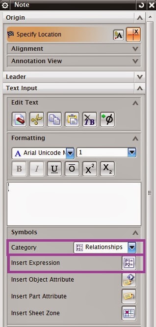
1. Create the note and add the expression of the model. 2. Tools > Expression  and change the parameter values. No need to change the workbench  or application to modeling.

NX_Kinematics

Image

Unigraphics-NX-8.5-Core & Cavity Extraction-Mould Wizard-Video Training

Image

Unigraphics-NX-8.5-Core & Cavity Extraction-Mould Wizard-Video Training

Image

5 NX Mold Wizard Parting Surface

Image

NX8 - Progressive Die Design - ZarzÄ…dzanie zmianami

Image

Unigraphics NX PDW - Standard parts

Image

NX CAD - NX 8.5 - Surfacing from Scan

Image

NX 8.5 Global Shaping

Image

What's New NX 8.5 Part 1

Image

Successful Continued Modeling and Manufacturing - NX

Dear Sir, Please find the links (download)  for Successful Continued Modeling and Manufacturing When Using Imported Data . https://groups.google.com/forum/?hl=en&fromgroups=#!topic/nx-cad-cam-chennai/BPNluWpj4zc Best Regards MATHI K  

ugpc utility in ugii folder - NX8

Image
    Q:   Is there a way to know which assemblies depend on a particular part file?     A1:   Inside NX   Information --> Assemblies --> Where Used. Now you can select where you want to search. It will only find the parts in the folders you search.     A2:   Outside NX               Check out the "ugpc" utility for command line options outside of NX. Here is an excerpt from the NXDocs: -p Lets you specify the search directories for ugpc to check when looking for component parts.     Drag and drop ugpc.exe         Check out the other options too…         Best Regards MATHI K  

NX 7 Tips - Assembly Interference

Image

siemens nx8 feder part 3 - helix lawcurve - bridgecurve - expressions - ...

Image

siemens nx8 feder part 3 - helix lawcurve - bridgecurve - expressions - ...

Image

trennwand siemens nx8 surface training - trimmed sheet - sew surfaces

Image

NX CAD Hints and Tips - How to rapidly create a gasket with sketch

Image